This is the second in a short series of three investigations I am doing on movable assemblages in 3D printing, as part of an Independent Study course at OCAD University. My process involves researching a particular joint or basic assembly followed by the creation of a 3D print incorporating the element in a creative manner, with documentation images and notes along the way.
It should be noted that this exercise / post in particular documents my learning process for Autodesk Fusion 360 rather than being a more creative exploration.
Hinges are a type of joint that rotate on one axis, as opposed to the full rotation of the previous week’s Ball joint. They are most frequently used for doors and lids; they allow freedom of movement along the rotational axis while providing load-bearing properties perpendicular to the axis.

Hinge designs are often designed in consideration of several factors including those listed below:
- Center of gravity
- Shape of the attached element
- Security and Visibility of joint
- Freedom of movement (rigid or free rotation)
- Separability
To respond to these factors, hinges are designed in different load-bearing shapes, with or without removeable pins or separable elements, internalized or external components, and/or restrictions on rotation.


In some cases, the hardware that the hinges are to be connected to is designed with recesses to accommodate the form of the hinge, as opposed to a surface-mounted application. This allows for more recessed or hidden designs, as well as more dynamic ranges of movement (e.g. as demonstrated in the ‘euro-style’ and ‘barrel’ hinge).

The pivot hinge, which rotates around a pin, is perhaps the most varied in its design forms among hinges as its designs tend to affix in non-conforming manners, as demonstrated in the search results in the figure above.
Movement of the mechanism can be limited or controlled by incorporating engineered elements into the design of the rotation mechanism (roughly ordered by the level of engineering required for their manufacture):
- Standard hinges are generally free-swinging with little resistance.
- Detent and bistable hinges automatically move to specific positions.
- Friction hinges incorporate adjustable tension to modify the resistance between the hinged joints.
- Spring-loaded hinges apply a constant force in one direction of movement
- Counterbalance hinges allow heavier objects to be moved with reduced effort
- Damping hinges applied a controlled movement when engaged


Figure 5: Spiral-like ‘fashion’ hinging mechanism (Stevenson, 2015)
A cursory search of 3D printed hinges did not reveal much in terms of variation from these standard designs, although I did come across some inspiring designs including tank tracks and interlocking ‘scale’ fashion. The images in Figure may have more in common with the ‘saddle joint’, which similarly to the standard hinge has a fixed rotation but is connected more loosely along a ‘rail’ element; I will be investigating woven elements such as these in a later investigation.

I also came across a research initiative that replaced a hinged part with a 3D printed alternative. Instead of opting to replicate the hinge, the research team decided to create a version that used the flexible properties of printed plastic as an alternative to the mechanical joint (see Figure). Presumably, this reduces the amount of wear and tear the plastic replica would have otherwise been subject to, knowing that such plastic is vulnerable to grinding.
—
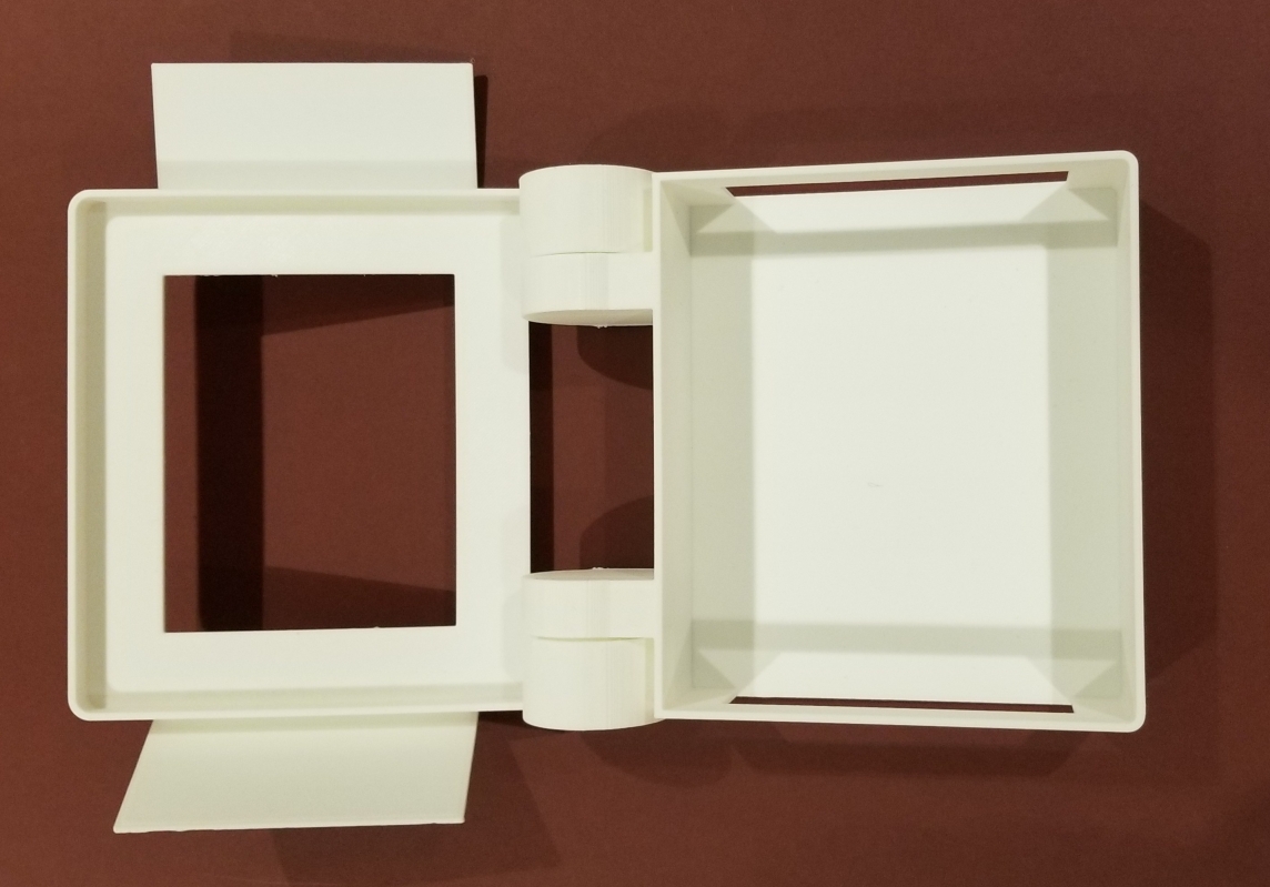
For this project, I decided to complete a long-overdue project of creating an enclosure for a MIDI-controlled Arduino project I developed with two friends for the purpose of controlling LED lights with an electronic drum pad.
When working in 3D, my usual go-to software application to model with is Rhinoceros. It is an excellent design software augmented for Parametric modelling with the Grasshopper plug-in, but with this project I wanted to take my first stab at learning a new and industry-standard software called Autodesk Fusion 360. Conveniently, there happens to be an easy-to-follow tutorial on the web that specifically teaches the software by modelling a hinged enclosure. With this in mind, my plan was to follow this tutorial and then make my own version based on my own project specifications.
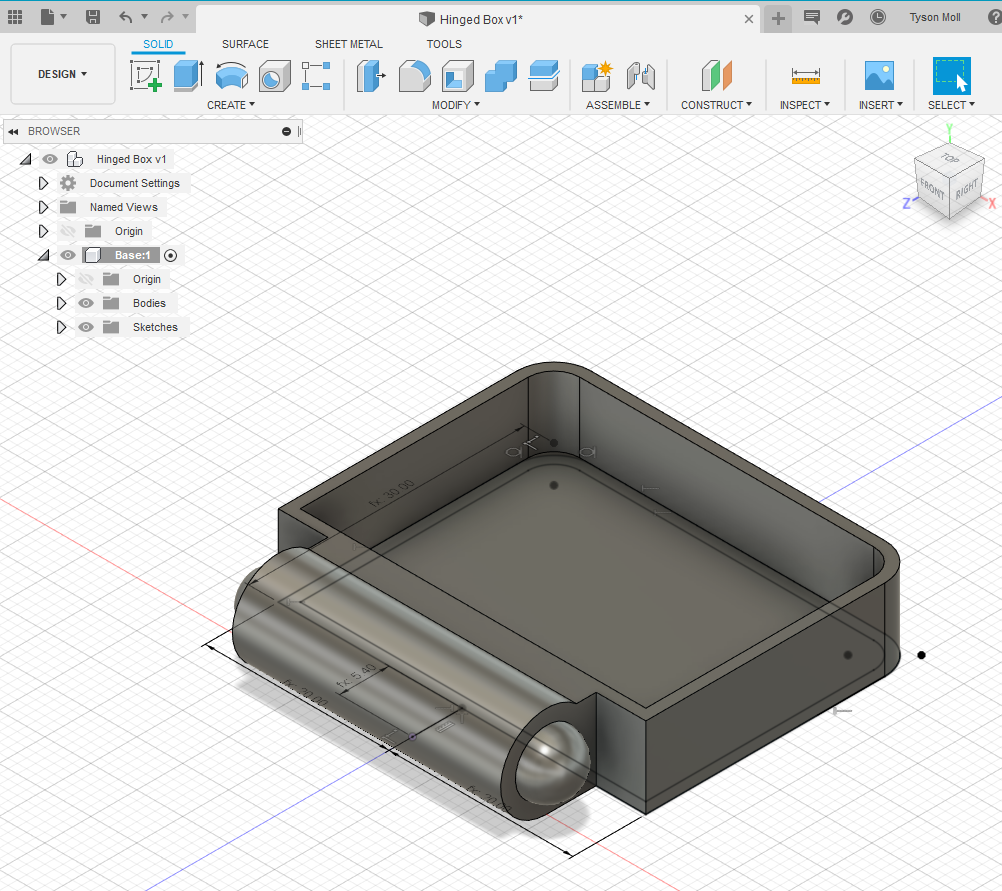


Figure 7: screenshots and .gifs from my work in Autodesk Fusion
To save time, I adjusted the parametric parameters of the tutorial model to my desired dimensions and worked from the drawings I produced while following the tutorial. I added two flaps to conceal otherwise exposed elements of the electronics and removed some solids to reduce the amount of material and time required for printing. In the past, I printed a hinged cartridge holder that had the clever idea of using 3d printer filament as the pin component, so I reused the idea in my design of this enclosure’s hinges by specifying a pin hole size of 2mm for the door hinges.
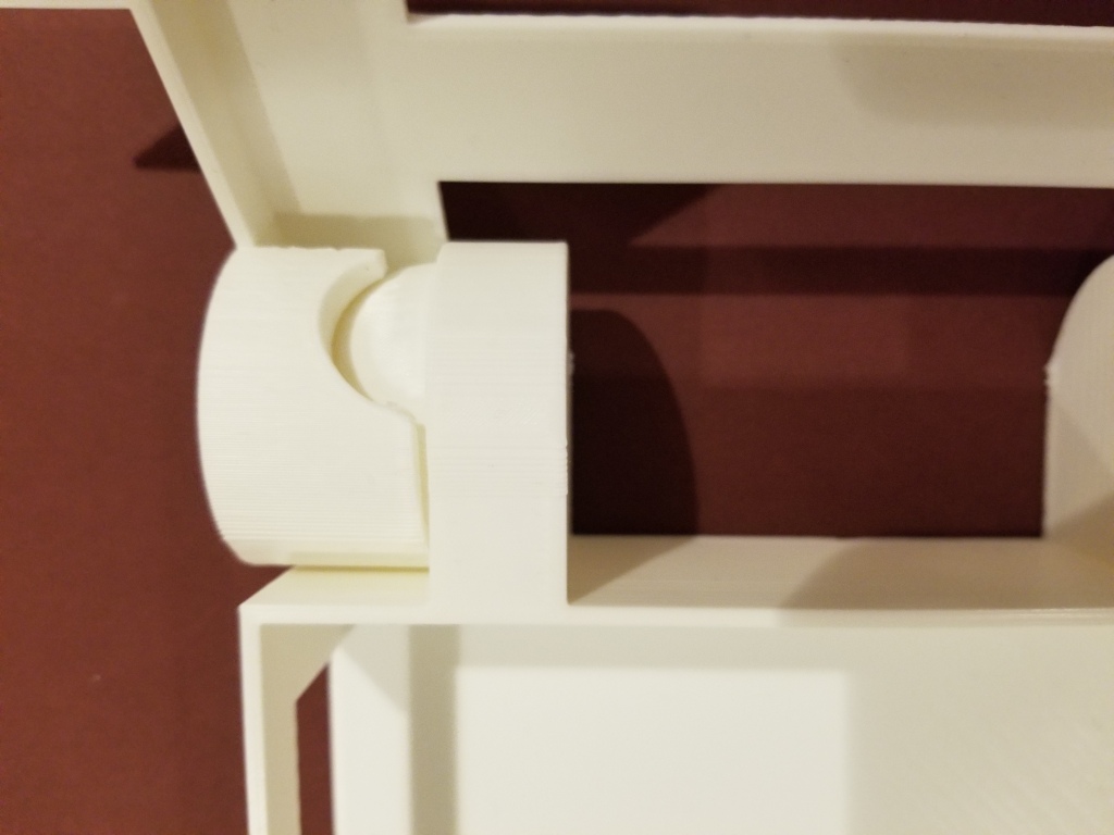
Printing the doors took about 2 hours, while the lid and base took approximately 13 hours. Since the lid and base would not fit on my printer bed together, I created a notch in the lid element to make the connecting of the two elements easier.

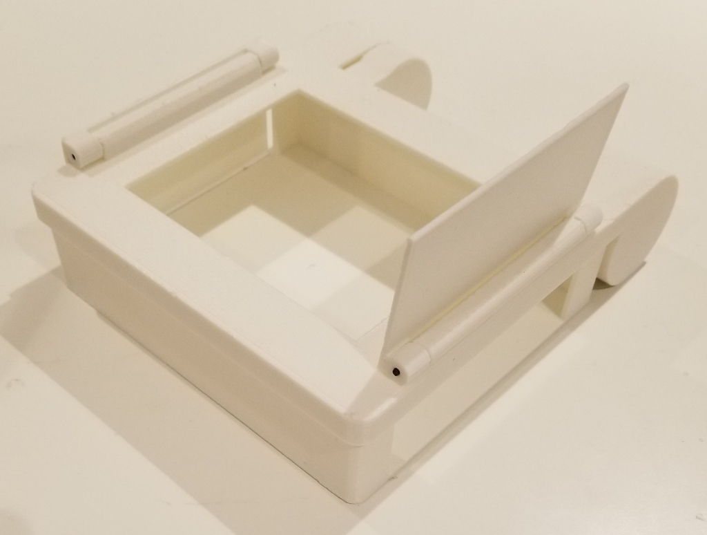


This project ended up being more of a learning opportunity than a creative exploration, but I’m happy to say that I feel much more comfortable with Autodesk Fusion 360 than before. I am not quite sure how Fusion 360 can handle more complex geometries that I take for granted in Rhinoceros’ modelling, as the method I learned was very specific in its approach to creating the assemblage, but I look forward to learning more about this software and perhaps using it in association with my existing modelling pipeline to create larger assemblages.
References:
Jana, Prabir. “3d Printing of Machine Parts: A Research Initative by NIFT”. Apparel Resources, May 19, 2017. https://in.apparelresources.com/technology-news/manufacturing-tech/3d-printing-of-machine-parts-a-research-initiative-by-nift/
Langnau, Leslie. “Key Decision Points in Hinge Hardware”. Design World, November 11, 2016. https://www.designworldonline.com/key-decision-points-hinge-hardware/
Lennart & Industrilas. “Learn about different types of hinges”. Youtube, April 3, 2013. https://www.youtube.com/watch?v=8zaW6Zp1c_g
Rockler. “Choosing the Right Hinge for Your Project” Rockler, November 7, 2018. https://www.rockler.com/learn/choosing-the-right-hinge-for-your-project
Stevenson, Kerry. “What is it Actually Like to Wear 3D Printed Fashion?” Fabbaloo, September 22, 2015. https://www.fabbaloo.com/blog/2015/9/16/what-is-it-actually-like-to-wear-3d-printed-fashion
